Repairing a W111 Mercedes Fintail Fuel Pump
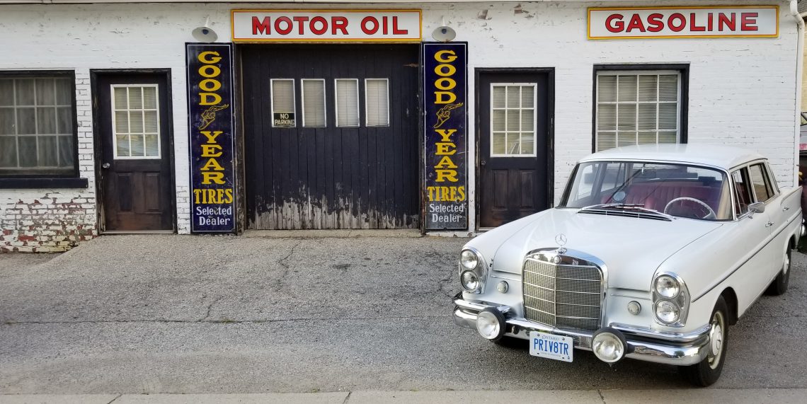
Returning home to Frontseat Driving HQ in the daily driver, we were surprised to see a puddle under our Fintail Mercedes that had been sitting idle overnight. The bigger surprise was that it turned out to be fuel not coolant.
It isn’t often a vehicle is generous enough to break down in the driveway. Perhaps it was her way of thanking us for the fun, and doting she’s enjoyed so far.
Driving a vintage car can be a unique experience, maintaining one a challenge, and finding parts to repair one nearly impossible. So far we’ve been shocked at the availability of parts for the Fintail. In fact Mercedes Classics carries nearly every part we’ve inquired about – nearly every part.
While our immediate assumption was that a line had ruptured it quickly became evident that the pump itself was leaking from the weep holes, a sure sign that the diaphragm was damaged.
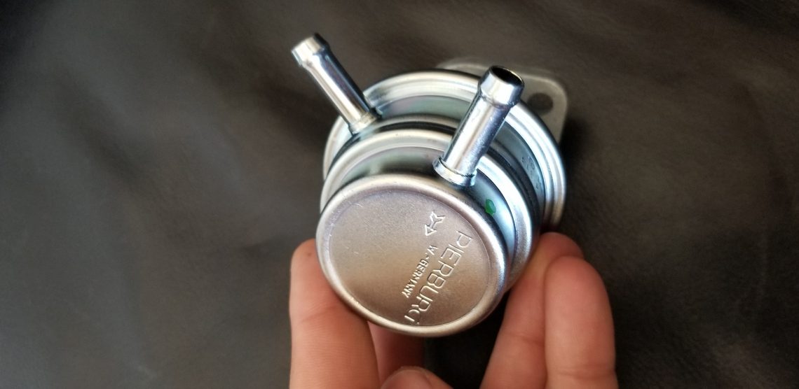
In normal operation the fuel enters and leaves from the same side of the pump. The holes worn through the diaphragm however were allowing the fuel to spill out the backside of the pump casing and out the weep holes and onto the hot engine clearly a dangerous situation.
The entire pump splits into three pieces. The part circled in red remains bolted to the engine block.
The part circled in blue is still attached to the fuel lines and is left hanging in the engine bay.
The diaphragm that needs to be repaired is found but not shown in the section of the pump highlighted in yellow.
Mercedes exploded diagram of the pump.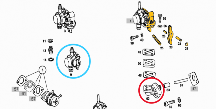
Weep holes on backside of pump body (yellow in above diagram).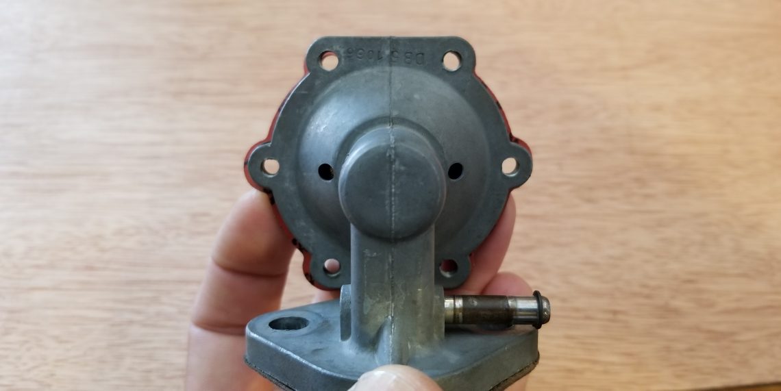
Pump housing (yellow in above diagram) showing diaphragm.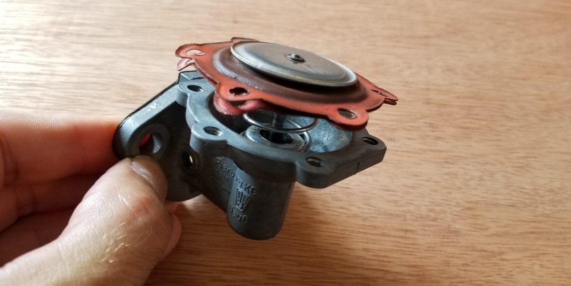
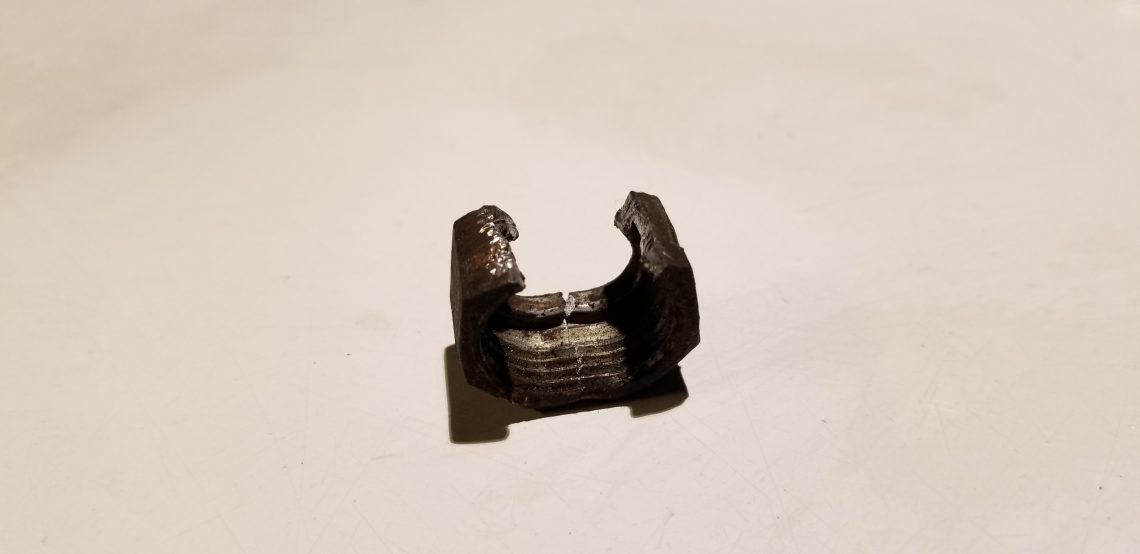
A hole through both layers of the diaphragm proves to be the culprit.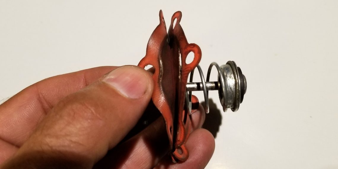
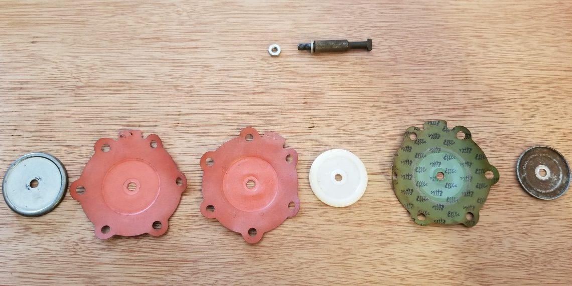
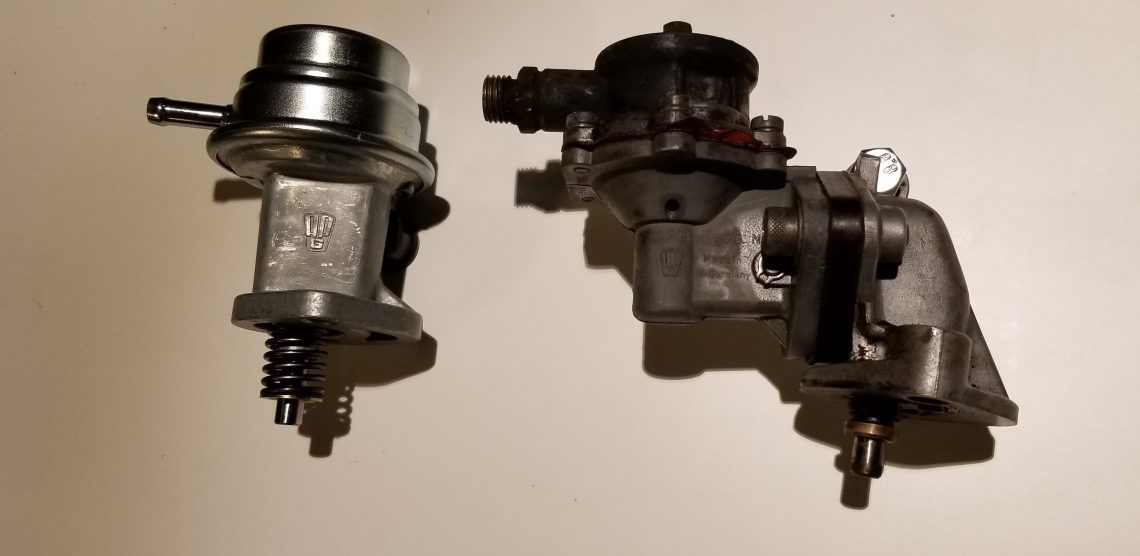
Okay so the problem had been found, now came the time to find the replacement diaphragm. Unfortunately unlike many fuel pump diaphragms our unit doesn’t disassemble any further than pictured, so the spring, seal, rod, and diaphragm must be replaced as an entire unit. Not only is it not offered by Mercedes Classics, it doesn’t even appear on the exploded Mercedes fuel pump diagram.
While a new replacement pump is available it isn’t cheap, and it’s shiny. Ideally we want this car to retain as much of it’s dirty original parts and patina as possible.
A couple years ago, before the Fintail was even purchased we came across a forum post claiming that Fiat part number 0009918453N was a suitable replacement and that factoid was filed away for future reference. Going with that vague info, we found and ordered the part from C. Obert & Company in Santa Cruz, California.
The Fiat diaphragm is a more typical example of a replacement part in that it disassembles to it’s component parts which can be individually changed out. That said, the Fiat part is by no means a suitable replacement as can be seen in the following photos.
Here the similarities of the Fiat part, on the left are obvious.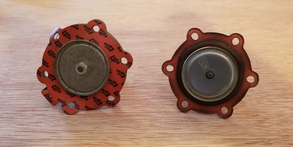
Here the differences, again Fiat part on the left are obvious.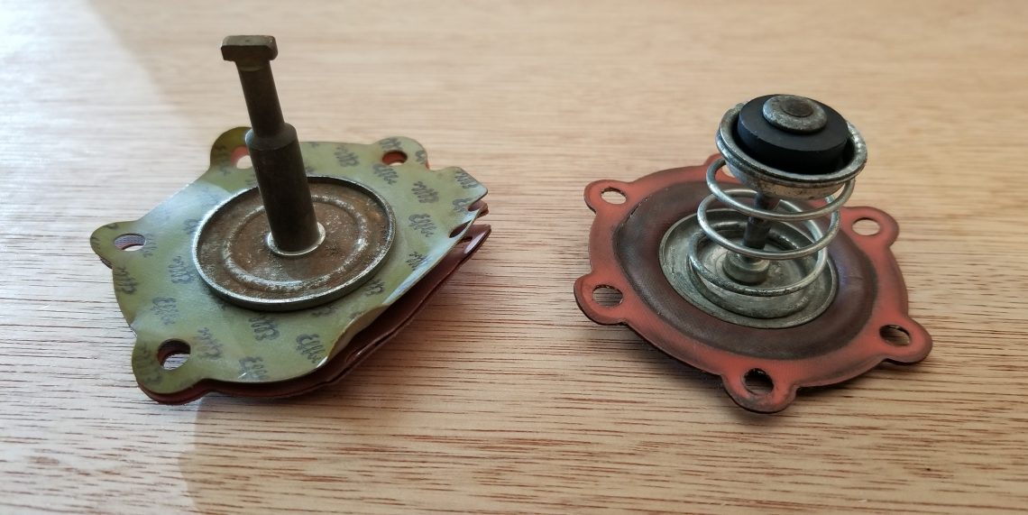
Length of the Mercedes pump rod vs…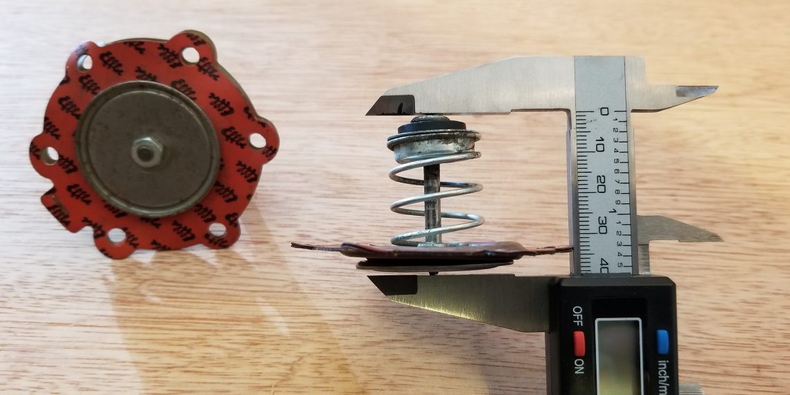
…the Fiat pump rod.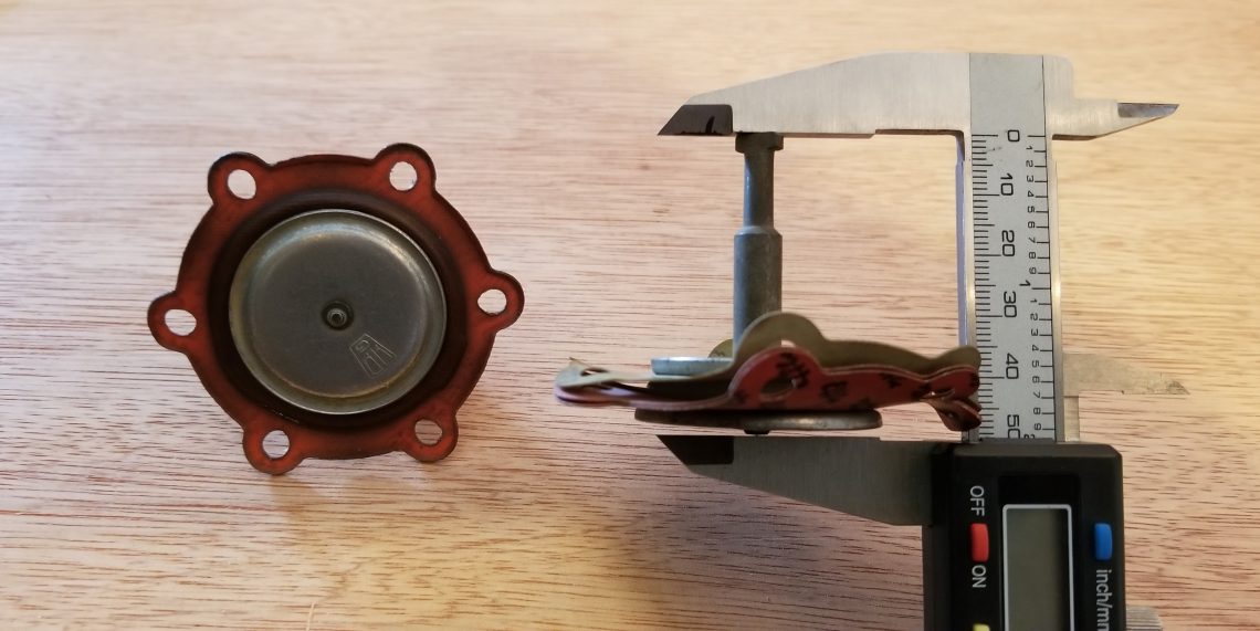
Here the diameter of the Mercedes pump rod is compared to…
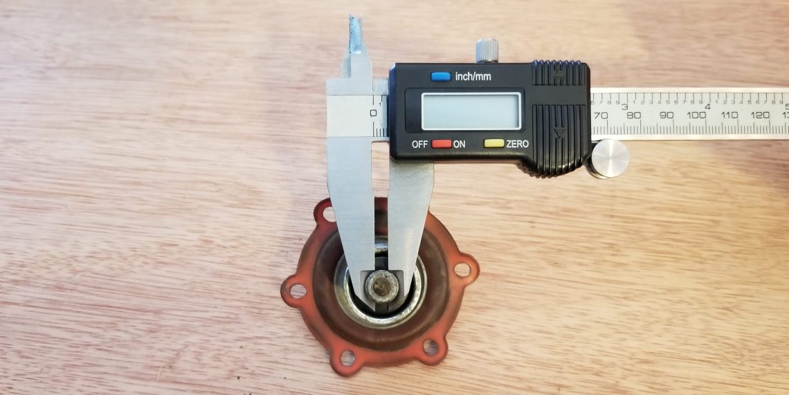
…the diameter of the Fiat pump rod.

Initially it occurred to us that perhaps with a bit of minor surgery we could adapt the Fiat pump rod to the Mercedes. It quickly became clear that the required alterations would be much more than minor surgery. For now the idea of altering the rod has been shelved while we investigate an easier approach.
Our revised approach involves disassembling the Fiat part, and using the diaphragm material on the Fintail pump. At this point you might be saying, “But wait, didn’t you say the Mercedes part didn’t disassemble?”
Yes we did.
The Fiat diaphragm disassembled.
Socket used to carefully cut the diaphragm.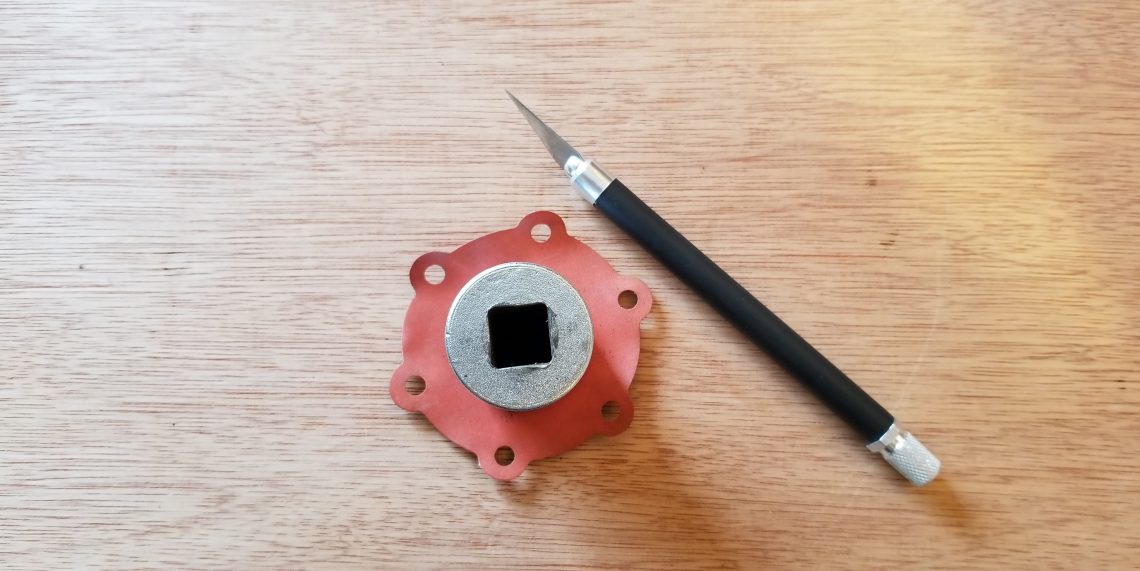
Fiat diaphragm with hole carefully cut.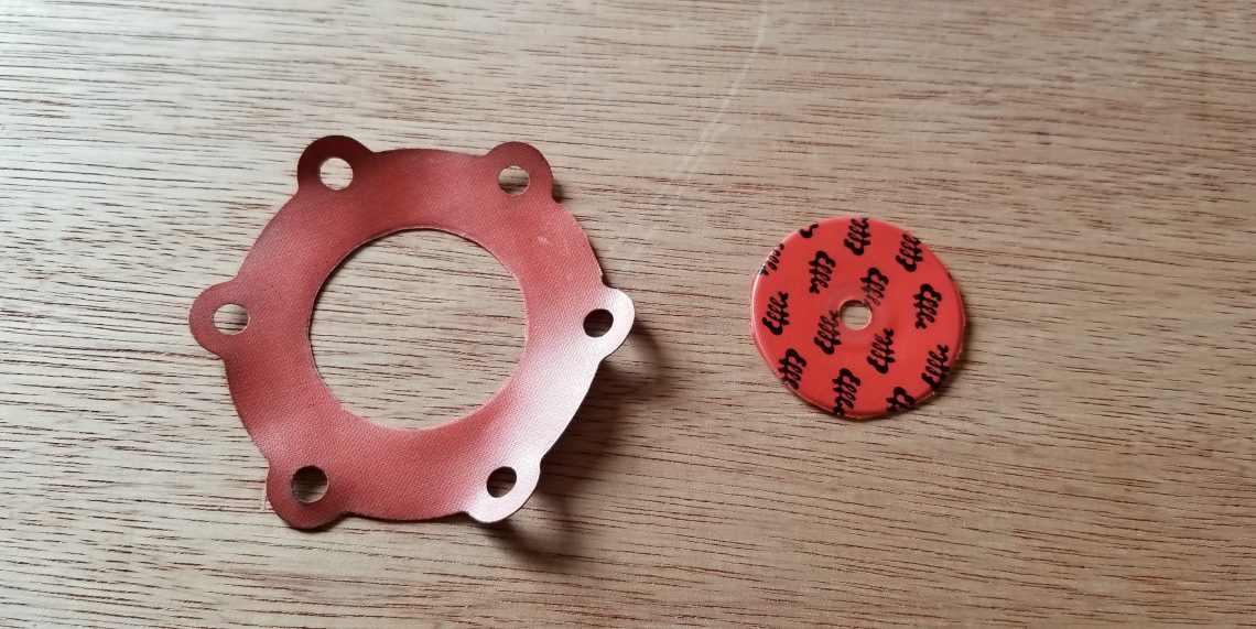
While the diaphragm material looked to be about the same size and the bolt hole pattern the same, it really was tough to tell. We took one of the layers of the Fiat diaphragm and using a hobby knife and an appropriate sized socket as a cutting guide we cut a hole in the material big enough for it to fit around the Mercedes’ spring.
Fitting the newly cut Fiat diaphragm over the spring and between the two layers of the Mercedes diaphragms it proved to be a near perfect match.
By now the secondary plan of attack is probably becoming clear. While the new layer of diaphragm fit well, it alone wouldn’t be capable of preventing fuel from travelling to the other side of the pump because it isn’t sealed along the inner diameter. The next step then was to try gluing the old diaphragm to the new diaphragm. While the diaphragms looked like butyl rubber and smelled like it too, were they? An experiment with a couple of scraps, seemed to confirm it.
Near perfect match.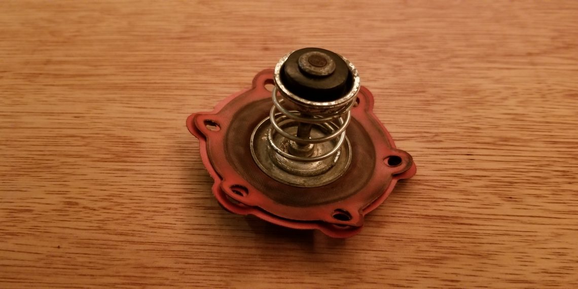
Sticking together but will fuel dissolve the glue?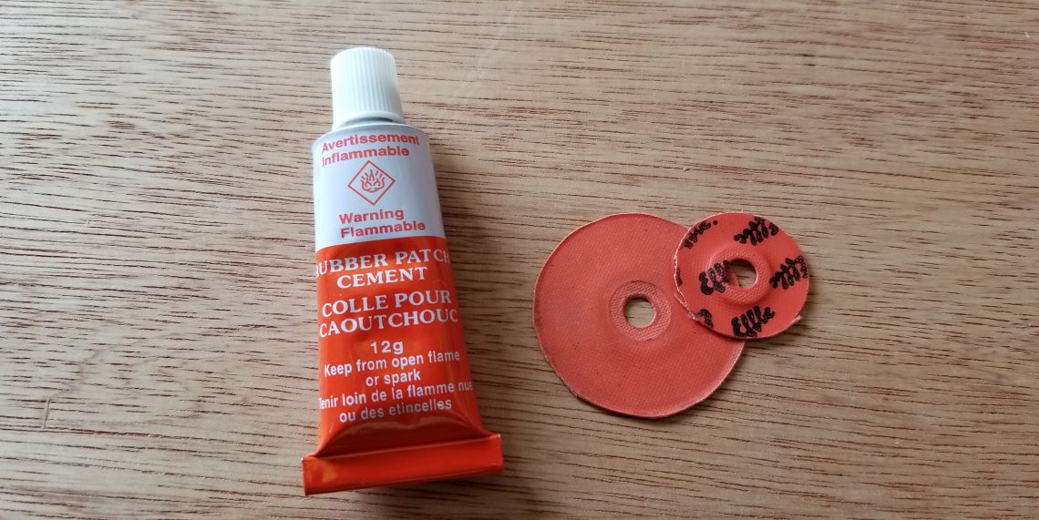
The result, as suspected that the glue did not hold up to the effects of gasoline. Tomorrow, we will try a glue known to be gasoline resistant. We will update this post as soon as we have results. Rather than wait to post this blog entry until the project was completed (successfully or not) we thought we’d publish it now to solicit some input. Perhaps with the above details you might imagine a good approach. Maybe you have repaired one yourself, or better yet you have a lead on a replacement. Feel free to comment below with any ideas, or questions, and stay tuned for the update!
This cement is fuel resistant, and currently curing.
Both surfaces were scored.
Glued and clamped
After a couple days of glue, clamp, and repeat the finicky job of gluing the two diaphragms together was complete. It looks promising folks! That said, we have a new mechanical pump in transit. While we aren’t thrilled with the replacement (more on that when it shows up) we found it much cheaper than that we first sourced. If nothing else the replacement will serve as good research.
Time now to reassemble the OEM pump;
- the spring plate slips into the actuator lever.
- the open spring end fits over a post in the pump body.
- the pump seal is fit into place on the pump body.
- the spring is compressed while the pump rod is extended.
- the rod mates to the actuator simultaneously.
From left to right the parts are assembled.
The yellow circle shows the placement of the spring.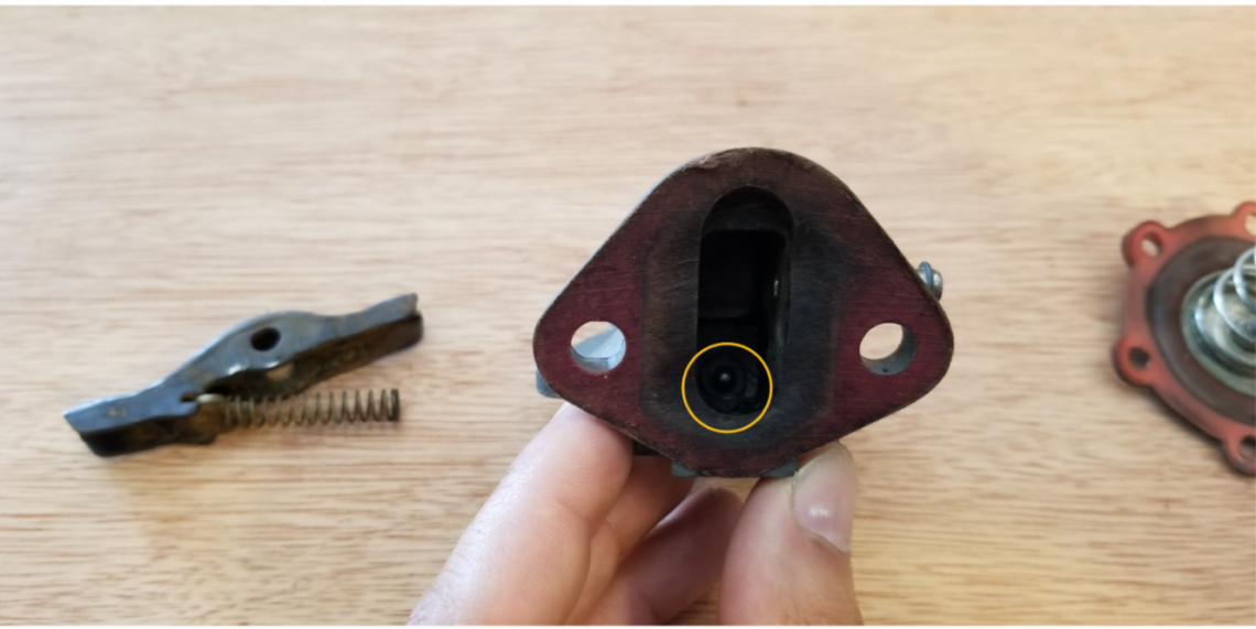
In the center of the pump the fork of the actuator lever is visible.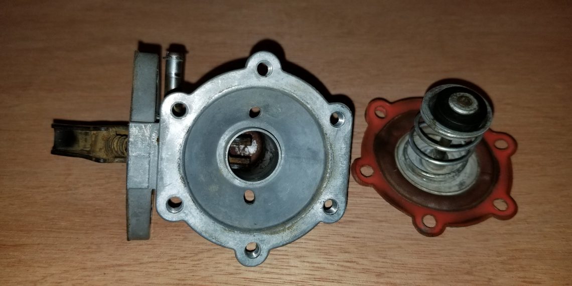
This shows how the diaphragm rod mates to the actuator fork.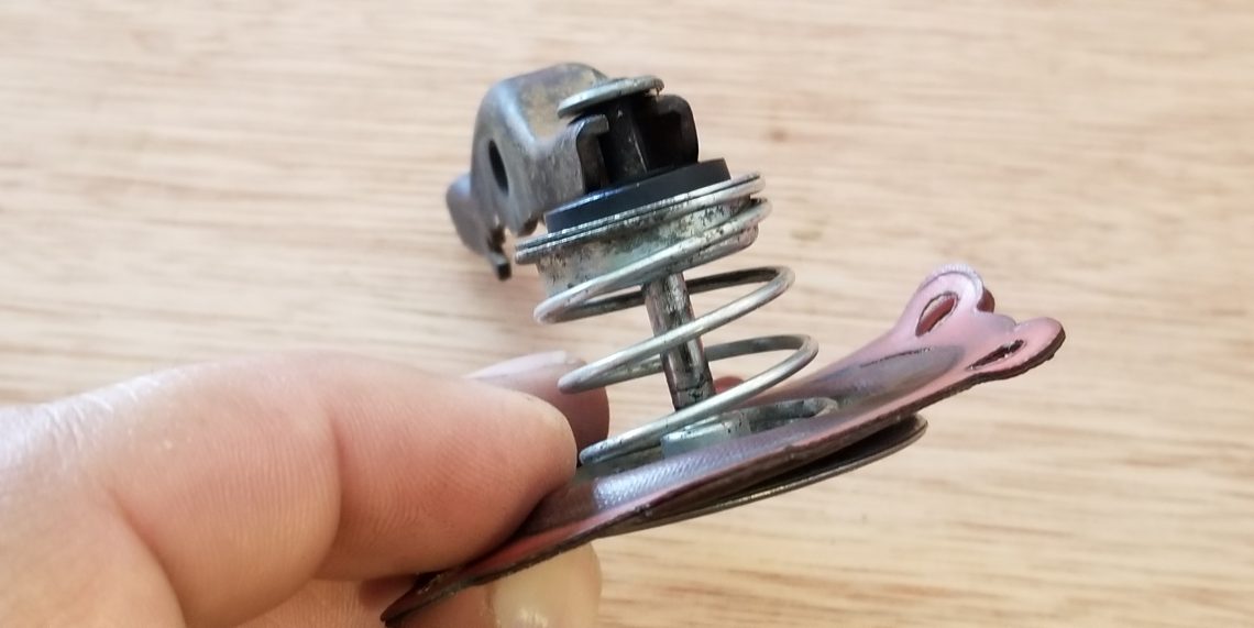
So our repair worked! For a week. While we would have liked to continue the experimenting with glues our schedule of events was just to busy to continue. By the time the repair failed we already had the replacement pump in hand.
As mentioned we resisted replacing the pump as we really would prefer to repair or renew old parts rather than simply replacing them with new. Not only was a new pump against our philosophy, strictly speaking it wasn’t a direct replacement with the OEM part. Yes it worked, and was nearly a bolt on replacement but it clearly was of a newer design. The new pump is still non-rebuildable as it doesn’t even disassemble.
Visually the replacement pump design is different enough that it was only with the full assurance of Mercedes Classics that we ordered it. The new pump does away with the intermediate mount as seen in the exploded diagram above circled in red and numbered ’60’. The new pump bolts directly to the engine block thus the plunger of the diaphragm is activated directly without the rocker mechanism seen highlighted in yellow and numbered ’20’. The following photo shows the significant differences.
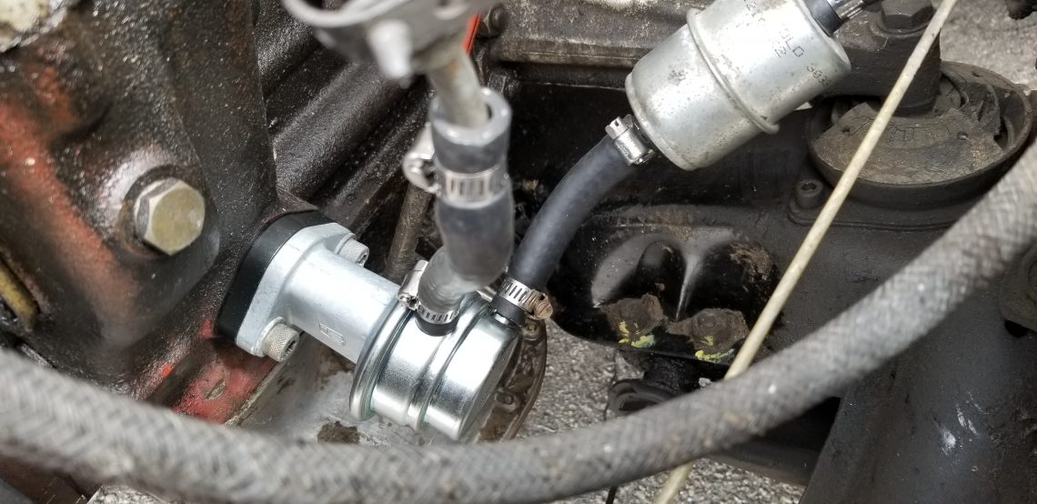
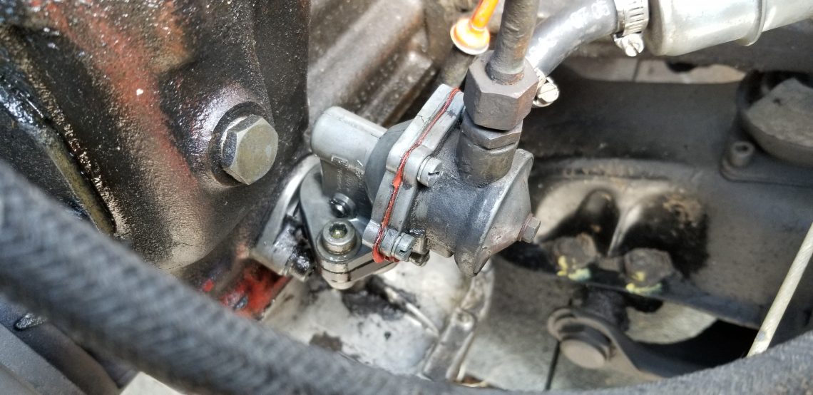
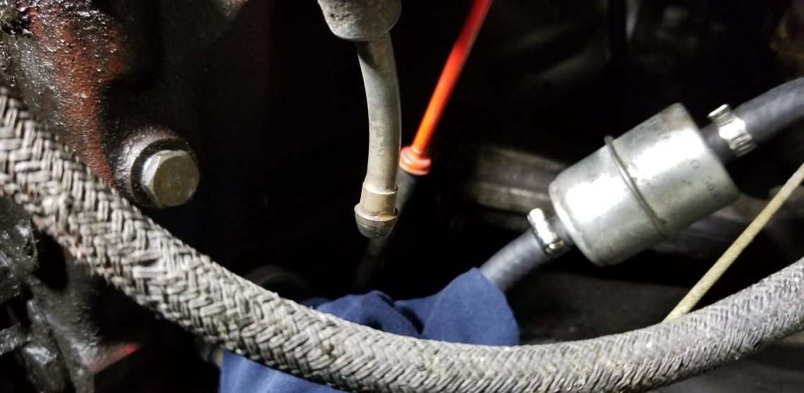
As mentioned the new pump is ‘nearly’ a bolt on replacement. The pump base seen below shiny and still attached to the engine block needs to be removed along with the rod, which is a straight forward task.
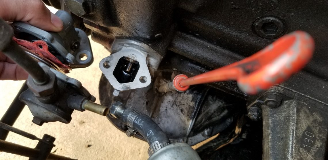
Additionally the new pump doesn’t use a threaded fitting for the pressure line as seen below. A few options are available here. The entire line can be replaced which means significantly altering the look of the engine and requires finding the appropriate hardware to mate back up to the Zeniths. This option was deemed as too much trouble and sacrifice for us. Another option would be to cut the line at the end nearest the pump. Not a bad option but we wanted a flared end for safety. Likely the line could have been flared easily enough however we thought we could skip a step, and we were right. We cut the OEM captured threaded fitting off of the line itself, leaving behind the factory flare.
After that, it was truly simply a matter of bolting the new pump, still using the original bolts, directly to the engine block. The new pump has been working flawlessly for many, many thousands of miles since.
As always if you have any comments leave them below. We are still searching for the correct diaphragm replacement, if for no other reason than to have a spare pump on hand. If you have any leads we’d appreciate hearing about them.