Helphos Spotlights 


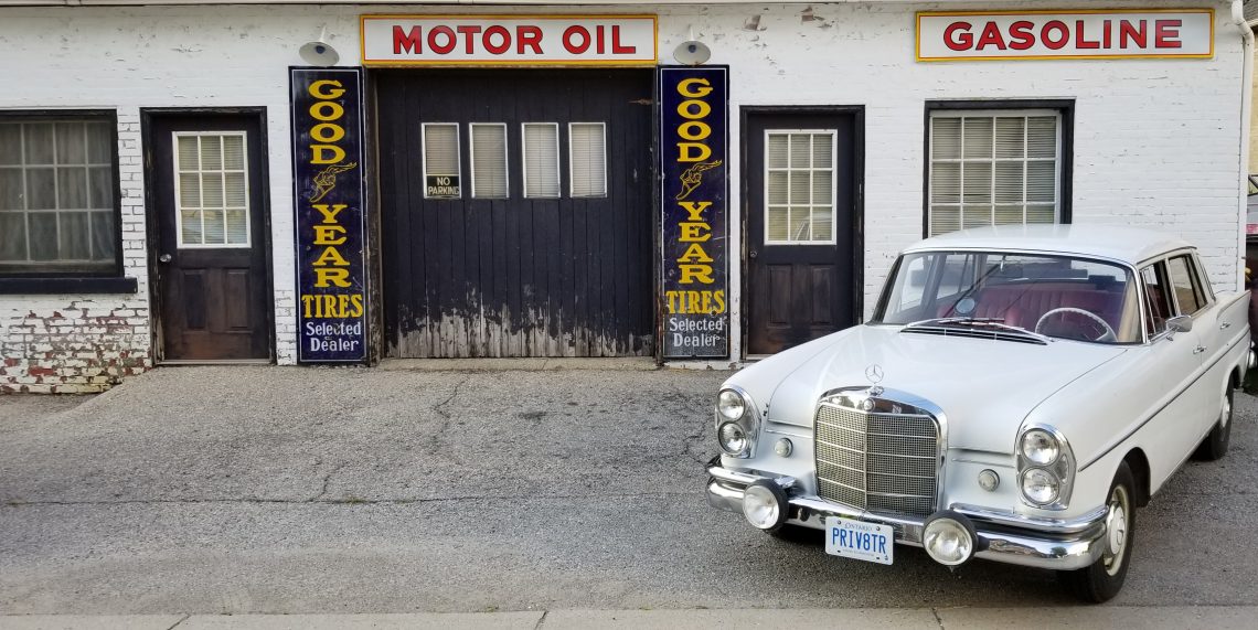
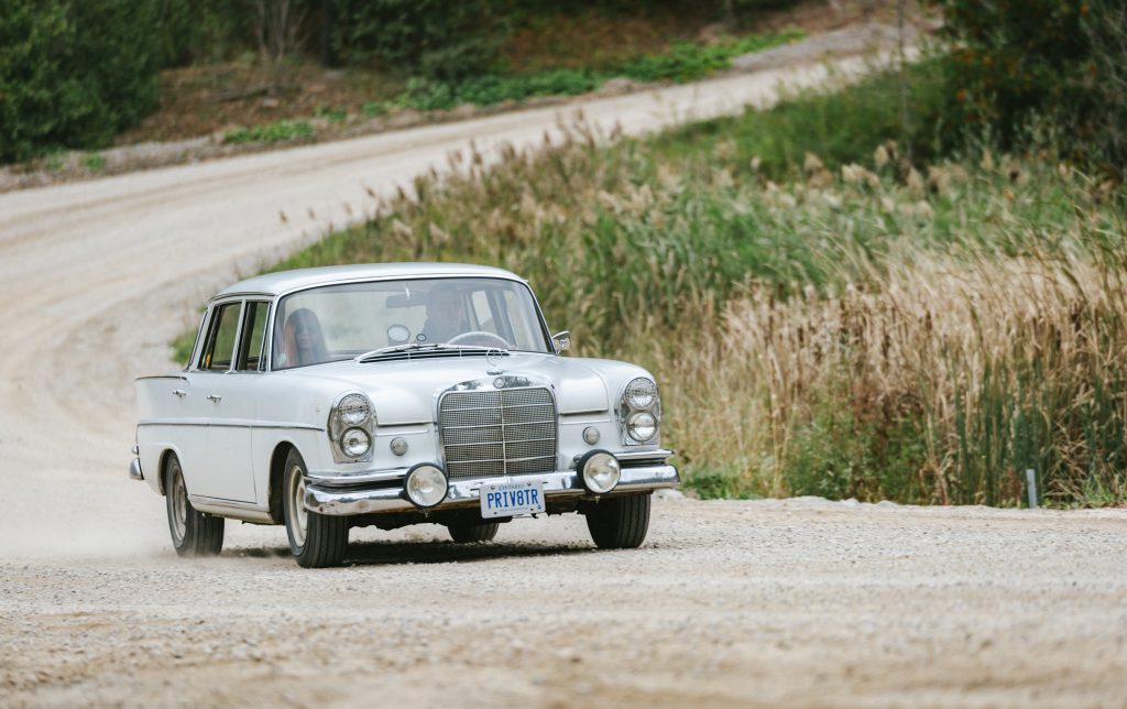
As many of you will know, our current love affair is a 1967 Mercedes W111, better known as the Heckflosse or Fintail in English.  As a rarely seen model it undoubtedly garners a lot of attention.

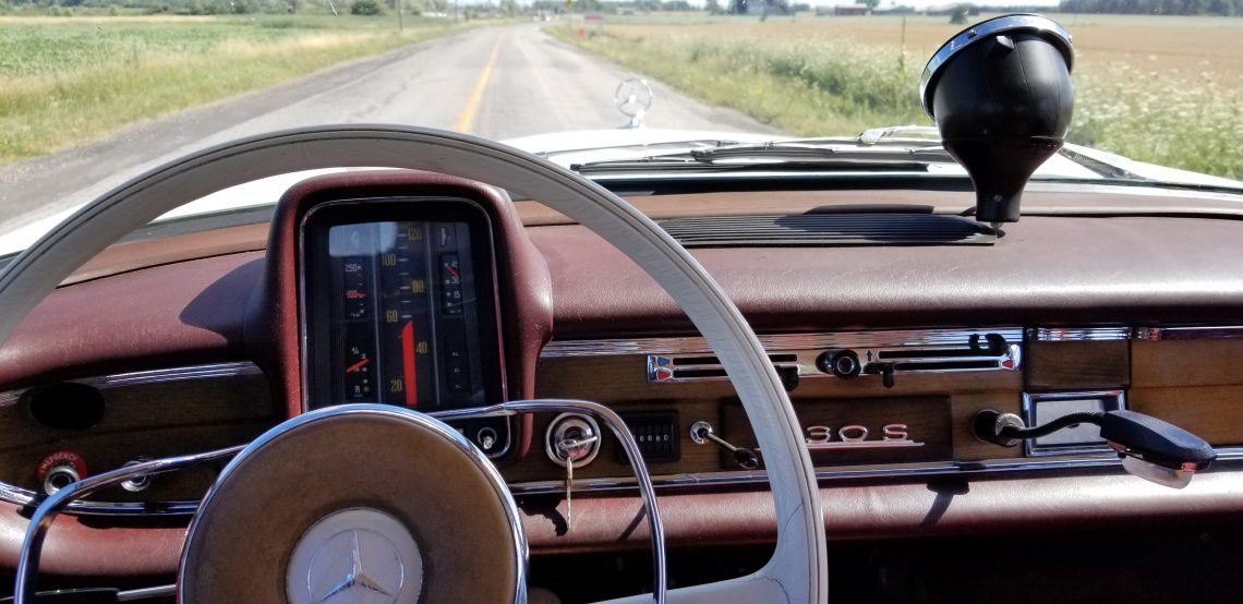
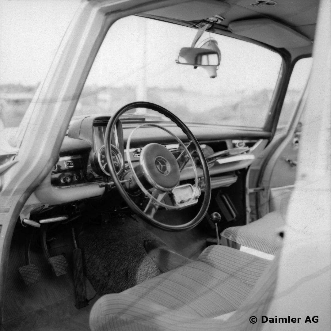
In period the Teutonic design was quite reserved, but these days the Mercedes star sitting atop the huge chrome grill, the flowing chrome adorned tail fins, and the vertical ribbon speedometer all attract a lot of interest.

It doesn’t take long though before the inquiring eyes fall upon the car’s greenhouse, and in short order the question always comes, “what’s that on the windshield?”


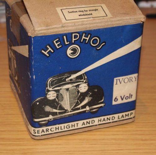
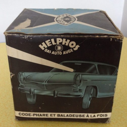
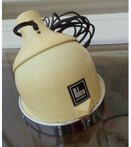
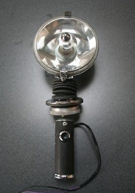
The Helphos “Eye of the Car” or “The Car Eye” is a German designed spotlight sold through the 50s and 60s that mounts directly to the windshield.  The above photos show the evolution of the packaging during that time.  The Helphos design was also rebranded under the names Polimatic, Polco (seen below), Les Leston, Marchal, and probably others.

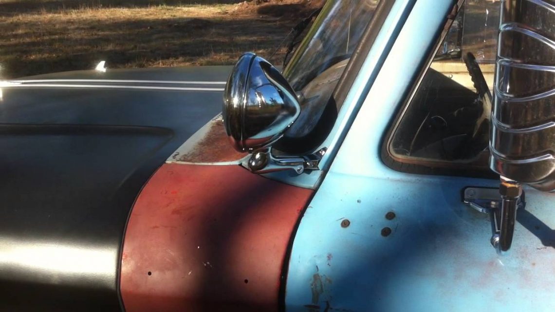
Many cars as early as the 1920s sported spotlights, as road illumination was far less common and most signage didn’t use reflective materials.  These spotlights were often attached to the A pillar or the front wing (fender) and required reaching outside the car to operate.  While many were strictly spotlights, combination units with a spotlight facing forwards and a mirror facing rearwards were a common accessory for decades right into the 60s.  Eventually however, spotlights mounted on and through the A pillar made it to the market. These were controlled from within the cabin via a handle and linkage and while quite common on police and fire vehicles were less common with the average car owner as few owners warmed up to the idea of drilling through the A pillar.

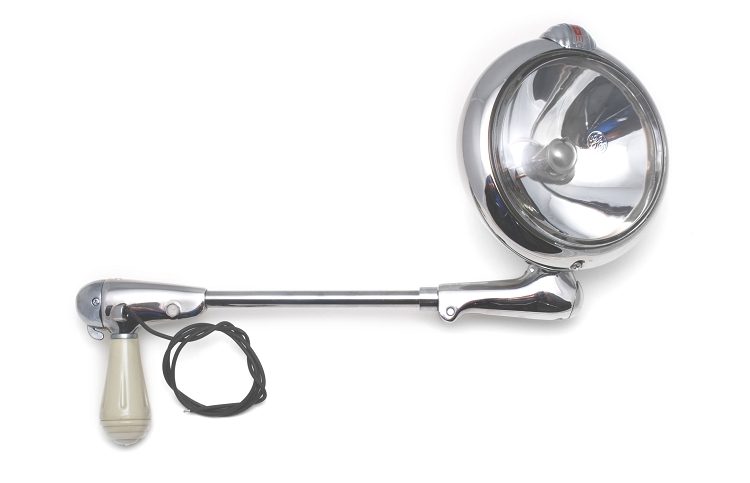
While the infamous British automotive electrics company Lucas had their own solution to reaching outside the cabin, it was not nearly so elegantly devised.  Lucas sold a roof mounted light that looked and operated much like a submarine periscope.  The light was unsightly and (with a large handle invading the cabin) intrusive.  Perhaps the biggest drawback was that it required drilling a hole in the roof of the car.  As such it really was only popular with the most dedicated British rally teams, and was never adopted by the general public as the Helphos was.

The Helphos spotlight was novel as not only could their design be used from within the cabin, the light itself was inside the cabin.  Not only was the user protected from the elements while directing and focusing it but the light was protected from damage from flying road debris.  All this was accomplished without alteration to the vehicle. Not only could the end user install the light themselves, with installation being non-invasive the light could be switched from car to car in an instant.

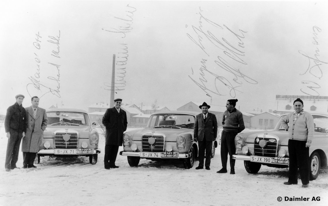
While popular for many recent years with the aircooled Volkswagen folks (who adore their period accessories) the Helphos spotlight is really otherwise unknown these days but for a niche group of period endurance or navigational rally enthusiasts.  While the Helphos light was used by many rally teams, Mercedes was especially fond of them. In fact it is rare to find a period photograph of a Fintail rally car where the vehicle is without one. 

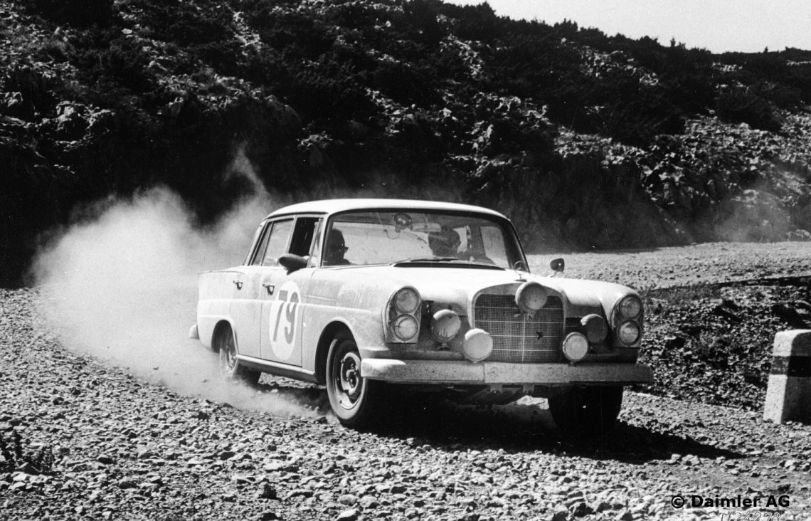
As we always envisioned building the Fintail into a ‘period’ rally car, it was practically essential to install one to complete the look.  We actually owned the light before taking possession of the car itself.  


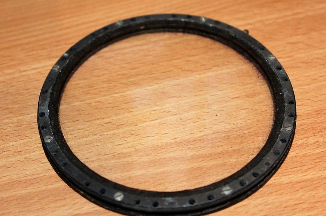
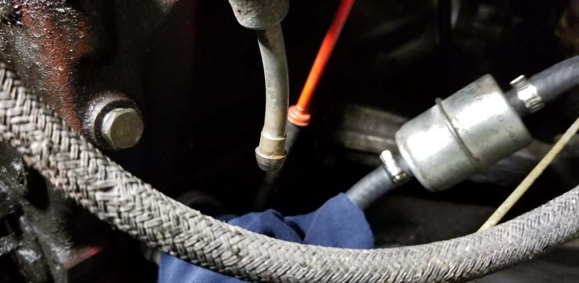
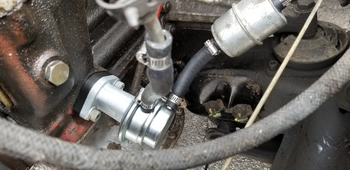
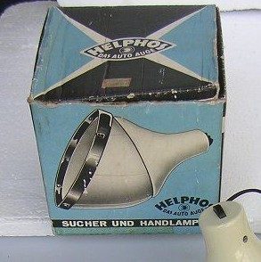
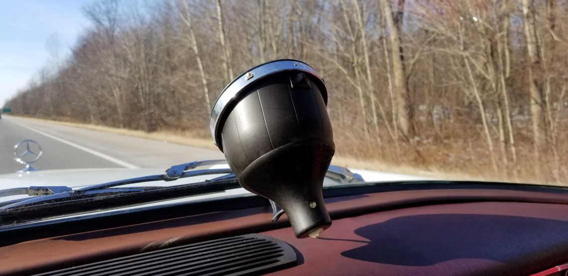
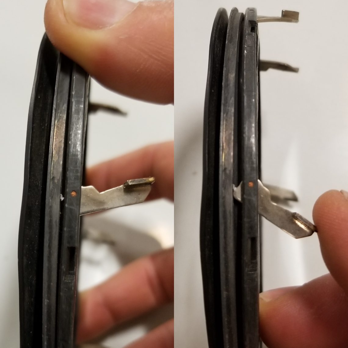
The light is actually comprised of two main parts, a metal mounting ring with embedded glass that attaches to the windshield and the light body itself that hangs from the mounting ring.  The early version of the mounting ring seen above was a simple design as the flat windshield screens of the time posed little challenge to adhesion.  However as curved glass became common the mounting design (seen below) necessarily became more complex.

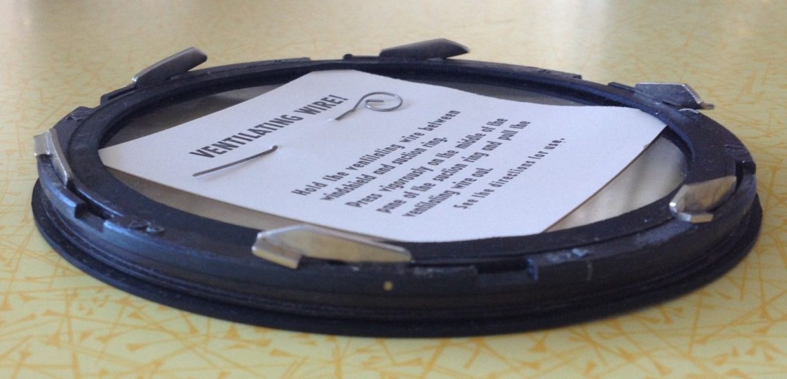
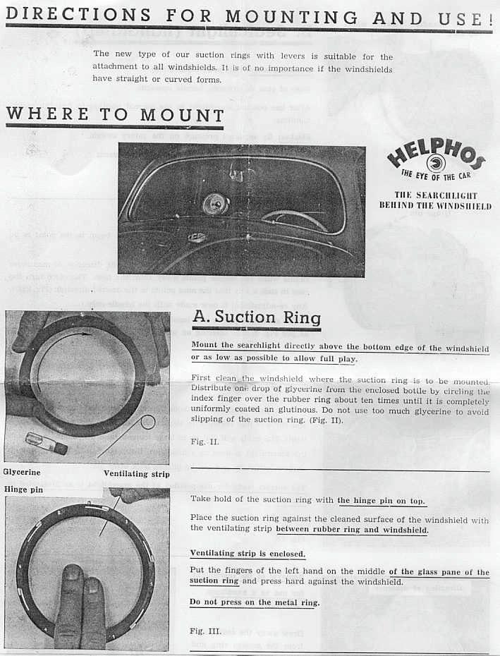
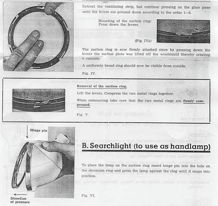
The later mounting ring is actually two separate hinged rings, with a rubber seal that is placed against the glass.   Numbered levers along the circumference of the ring are swung in consecutive order while the rubber seal (smeared with a dab of included glycerin) is pressed against the windshield.  A thin wire is included that is placed under the edge of the rubber gasket.   

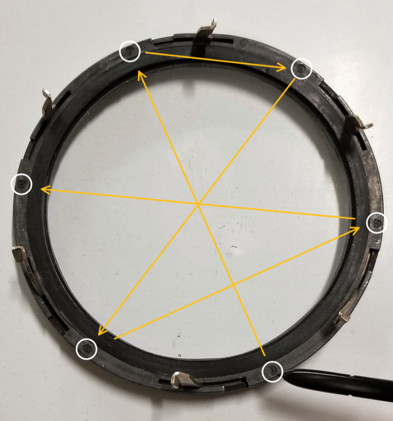
The wire allows the air trapped between the windshield and the mount to escape as the glass of the mounting ring is pressed towards the windshield.  The ventilation wire is removed and the levers are thrown pulling the two halves of the ring apart.  The result is an incredibly effective vacuum mount.

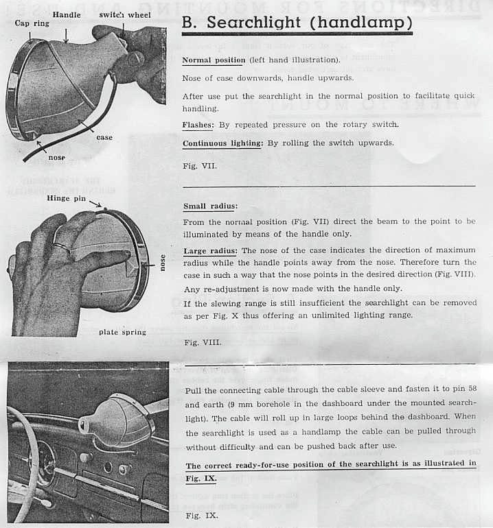
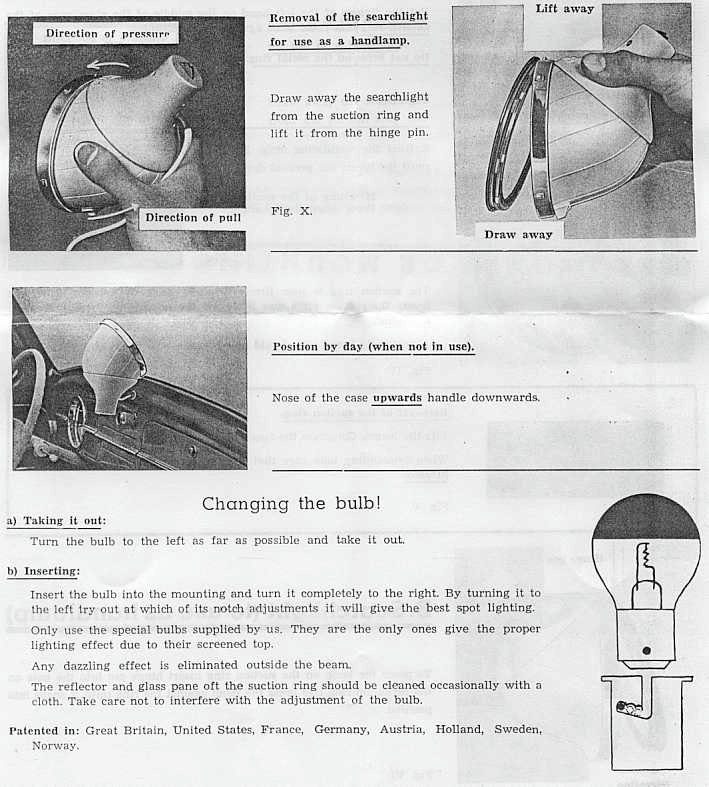
The main body of the lamp hangs from this ring and can be removed independent of the ring.  With the freedom provided by the included generous length of electrical wire,  the Helphos is effectively used as a handlamp for roadside repairs. Clearly this was another added bonus over most other available spotlights of the time.

While mounted on the windshield the light beam can be used to illuminate street signs, markers or roadside features.  The Helphos had another design advantage over most other spotlights as the beam itself could be focussed from narrow to wide beam simply by rotating the main body in a clockwise fashion.  Directing the chosen beam to the target was as simple as moving the handle.


While generally uncommon, the Helphos lights are still readily available in enthusiast circles, and eBay, even NOS (new old stock) lights are fairly common.  For the best prices, avoid any Volkswagen enthusiast sites, and German specific parts houses which tend to soak the eager enthusiast. Using some creativity in search terms and locations (these lights are far more common in Europe) along with some patience can save you enormously.  Ours came from England and even with the added cost of shipping we came a hundred or more dollars under the price of most North American sources.


While it’s best to confirm the electrical operation before purchase these are simple in construction, and easy to rewire if necessary.  While many Helphos lights now have male cigarette plug adaptors, in period they were sold with bare wire to install as the customer saw fit.  


Any potential buyer needs to ensure that the reflector and especially the rubber gasket are in good order.  A dried, torn gasket will absolutely prevent the light from adhering to the windshield, while a peeling or tarnished reflector will greatly reduce the light output.  


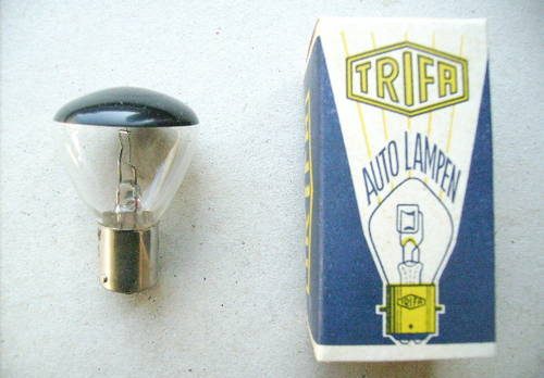
The bulbs, while still available, aren’t common and tend to range greatly in price.  Confirm that a bulb is included and working and consider combining the cost of shipping with a spare if the seller has them available.  The least expensive bulbs, lack the blackout painted end however this is easily replicated with some spray enamel.

The following are the Helphos installation instructions, explaining the mounting of the ring to the windshield, basic operations, and bulb replacement.

This article requires a couple acknowledgements.  First to Elliot Alder for the lead photo of our Fintail, one of our absolute favourites. 

Second a special thank you to Mercedes Benz that permits access to and use of the historic racing photography you see in the article.  

© Daimler AG.
All data and content are protected by copyright. Use of the data and content requires the source to be stated.
The global copyright remains the property of Daimler AG.

As always, comments and questions are welcomed.  We strive to provide accurate info however if you have spotted a mistake, or simply have more to add please let us know.  All our articles are perpetually updated and revised as needed.  

We’ll leave you with another historic Fintail rally photo – cars complete of course with Helphos lights.

We love Autumn.  We love driving. We love driving with friends.  

We especially love Autumn driving with friends.

We did just that Sunday past.

Some of our favourite roads and a few squiggles we weren’t familiar with were thrown into Google maps, a last minute invite was posted onto Facebook and before you knew it a cruise was happening.  

It never fails to awe how a machine can bring people together as the automobile has managed to do, for over a 130 years.

Our unlikely cast came from all walks of lives.  Quite a few decades separated the youngest from the oldest .  Several of us have only known each other for a few weeks, and most only met that day.  Yet when you throw the love of cars and driving into the mix any differences quickly faded into the background and a bond instantly solidified.

It is perhaps ironic that in an age where there seems so much strife due to differing political, religious, and social values the attack on the automobile is at its height.  Maybe rather than attack car ownership we should celebrate it, and encourage driving events, and car club membership to bring unity and fellowship.

Okay so admittedly we’re romanticizing a bit and straying dangerously near politics but the point is, it’s pretty cool how a machine can bring folks together.  Heck, for all its importance to society you don’t hear about refrigerator clubs, or refrigerator meets do you?!

Enough words.  Here are some pretty pictures.

The route snaked up and down the Niagara Escarpment in southern Ontario between Burlington and Orangeville.  Whether weaving your way up, flying down, or approaching from a distance the escarpment provides a brilliant backdrop at this time of year. 

Despite the ‘seat of our pants’ planning that was employed in organizing the cruise at least some effort was expended in choosing the route.  Some roads were hit from the direction providing the best driving experience, while others were approached with the best view in mind.  

The route took us through a number of quaint towns and hamlets including Limehouse, Glen Williams, Terra Cotta, Cheltenham, Boston Mills, Inglewood, and Belfountain where we stopped for coffee and some treats.

A big thanks to everyone for making it out, it’s always more fun cruising with others, we appreciate the company. 

This coming Sunday October 28 Frontseat Driving will be hosting yet another cruise, this time in the Niagara Region.

Expect a great variety of rolling country roads, tight winding technical driving, riverside and lakeside views, several waterfalls, and along the entire route a beautiful autumn backdrop. We’ll stop for lunch and drop into a couple of wineries worth the stop even if you aren’t a wine drinker. We’ll roll through many small hamlets, and towns and stop to explore several unique neighbourhoods along the way.

A very special thanks to Larry Strung not only for all the car photos seen in this article, but also for the great company in the Fintail.  The best backseat driver Frontseat Driving has experienced yet!  You can reach Larry at Larry.strung@me.com

We’ll leave you with this beauty – perfectly curated with autumn themed paint and a rolling ribbon of asphalt behind it.


Repairing a W111 Mercedes Fintail Fuel Pump


Returning home to Frontseat Driving HQ in the daily driver, we were surprised to see a puddle under our Fintail Mercedes that had been sitting idle overnight.  The bigger surprise was that it turned out to be fuel not coolant.

It isn’t often a vehicle is generous enough to break down in the driveway.   Perhaps it was her way of thanking us for the fun, and doting she’s enjoyed so far.

Driving a vintage car can be a unique experience, maintaining one a challenge, and finding parts to repair one nearly impossible.  So far we’ve been shocked at the availability of parts for the Fintail.  In fact Mercedes Classics carries nearly every part we’ve inquired about – nearly every part.  

While our immediate assumption was that a line had ruptured it quickly became evident that the pump itself was leaking from the weep holes, a sure sign that the diaphragm was damaged.

In normal operation the fuel enters and leaves from the same side of the pump.  The holes worn through the diaphragm however were allowing the fuel to spill out the backside of the pump casing and out the weep holes and onto the hot engine clearly a dangerous situation.

The entire pump splits into three pieces.  The part circled in red remains bolted to the engine block.

The part circled in blue is still attached to the fuel lines and is left hanging in the engine bay.

The diaphragm that needs to be repaired is found but not shown in the section of the pump highlighted in yellow. 


Mercedes exploded diagram of the pump.


Weep holes on backside of pump body (yellow in above diagram).


Pump housing (yellow in above diagram) showing diaphragm.


A hole through both layers of the diaphragm proves to be the culprit.

Okay so the problem had been found, now came the time to find the replacement diaphragm.  Unfortunately unlike many fuel pump diaphragms our unit doesn’t disassemble any further than pictured, so the spring, seal, rod, and diaphragm must be replaced as an entire unit.  Not only is it not offered by Mercedes Classics, it doesn’t even appear on the exploded Mercedes fuel pump diagram.  

While a new replacement pump is available it isn’t cheap, and it’s shiny.  Ideally we want this car to retain as much of it’s dirty original parts and patina as possible. 

A couple years ago, before the Fintail was even purchased we came across a forum post claiming that Fiat part number 0009918453N was a suitable replacement and that factoid was filed away for future reference.  Going with that vague info, we found and ordered the part from C. Obert & Company in Santa Cruz, California.

The Fiat diaphragm is a more typical example of a replacement part in that it disassembles to it’s component parts which can be individually changed out.  That said, the Fiat part is by no means a suitable replacement as can be seen in the following photos.  


Here the similarities of the Fiat part, on the left are obvious.


Here the differences, again Fiat part on the left are obvious.


Length of the Mercedes pump rod vs…


…the Fiat pump rod.


Here the diameter of the Mercedes pump rod is compared to…


…the diameter of the Fiat pump rod.

Initially it occurred to us that perhaps with a bit of minor surgery we could adapt the Fiat pump rod to the Mercedes.  It quickly became clear that the required alterations would be much more than minor surgery.  For now the idea of altering the rod has been shelved while we investigate an easier approach.  

Our revised approach involves disassembling the Fiat part, and using the diaphragm material on the Fintail pump.  At this point you might be saying, “But wait, didn’t you say the Mercedes part didn’t disassemble?”

Yes we did.  


The Fiat diaphragm disassembled.


Socket used to carefully cut the diaphragm.


Fiat diaphragm with hole carefully cut.

While the diaphragm material looked to be about the same size and the bolt hole pattern the same, it really was tough to tell.  We took one of the layers of the Fiat diaphragm and using a hobby knife and an appropriate sized socket as a cutting guide we cut a hole in the material big enough for it to fit around the Mercedes’ spring.

Fitting the newly cut Fiat diaphragm over the spring and between the two layers of the Mercedes diaphragms it proved to be a near perfect match.

By now the secondary plan of attack is probably becoming clear.   While the new layer of diaphragm fit well, it alone wouldn’t be capable of preventing fuel from travelling to the other side of the pump because it isn’t sealed along the inner diameter.  The next step then was to try gluing the old diaphragm to the new diaphragm.  While the diaphragms looked like butyl rubber and smelled like it too, were they?  An experiment with a couple of scraps, seemed to confirm it.


Near perfect match.


Sticking together but will fuel dissolve the glue?

The result, as suspected that the glue did not hold up to the effects of gasoline.  Tomorrow, we will try a glue known to be gasoline resistant.  We will update this post as soon as we have results.  Rather than wait to post this blog entry until the project was completed (successfully or not) we thought we’d publish it now to solicit some input.  Perhaps with the above details you might imagine a good approach.  Maybe you have repaired one yourself, or better yet you have a lead on a replacement.  Feel free to comment below with any ideas, or questions, and stay tuned for the update!


This cement is fuel resistant, and currently curing.


Both surfaces were scored.


Glued and clamped

After a couple days of glue, clamp, and repeat the finicky job of gluing the two diaphragms together was complete.   It looks promising folks!  That said, we have a new mechanical pump in transit.  While we aren’t thrilled with the replacement (more on that when it shows up) we found it much cheaper than that we first sourced.  If nothing else the replacement will serve as good research. 


Time now to reassemble the OEM pump;  


  • the spring plate slips into the actuator lever.
  • the open spring end fits over a post in the pump body.
  • the pump seal is fit into place on the pump body.
  • the spring is compressed while the pump rod is extended.
  • the rod mates to the actuator simultaneously. 


From left to right the parts are assembled.


The yellow circle shows the placement of the spring.


In the center of the pump the fork of the actuator lever is visible.


This shows how the diaphragm rod mates to the actuator fork.

So our repair worked!  For a week.  While we would have liked to continue the experimenting with glues our schedule of events was just to busy to continue.  By the time the repair failed we already had the replacement pump in hand.

As mentioned we resisted replacing the pump as we really would prefer to repair or renew old parts rather than simply replacing them with new.  Not only was a new pump against our philosophy, strictly speaking it wasn’t a direct replacement with the OEM part.  Yes it worked, and was nearly a bolt on replacement but it clearly was of a newer design.  The new pump is still non-rebuildable as it doesn’t even disassemble. 


Visually the replacement pump design is different enough that it was only with the full assurance of Mercedes Classics that we ordered it.  The new pump does away with the intermediate mount as seen in the exploded diagram above circled in red and numbered ’60’.  The new pump bolts directly to the engine block thus the plunger of the diaphragm is activated directly without the rocker mechanism seen highlighted in yellow and numbered ’20’.  The following photo shows the significant differences.   


As mentioned the new pump is ‘nearly’ a bolt on replacement.  The pump base seen below shiny and still attached to the engine block needs to be removed along with the rod, which is a straight forward task.  


Additionally the new pump doesn’t use a threaded fitting for the pressure line as seen below.  A few options are available here.  The entire line can be replaced which means significantly altering the look of the engine and requires finding the appropriate hardware to mate back up to the Zeniths.  This option was deemed as too much trouble and sacrifice for us.  Another option would be to cut the line at the end nearest the pump.   Not a bad option but we wanted a flared end for safety.  Likely the line could have been flared easily enough however we thought we could skip a step, and we were right.  We cut the OEM captured threaded fitting off of the line itself, leaving behind the factory flare.


After that, it was truly simply a matter of bolting the new pump, still using the original bolts, directly to the engine block.  The new pump has been working flawlessly for many, many thousands of miles since.  

As always if you have any comments leave them below.  We are still searching for the correct diaphragm replacement, if for no other reason than to have a spare pump on hand.  If you have any leads we’d appreciate hearing about them.